When your network adapters are installed, the next
step is to get your computers connected. Installing wiring can be the
most difficult task of setting up a network. How you proceed depends on
the type of networking adapters you have:
If you’re using wireless adapters, of course, you don’t need to worry about wiring. Lucky you.
If
you’re using phoneline networking, plug a standard modular telephone
cable into each phoneline network adapter and connect them to the
appropriate wall jacks. The adapter must be plugged directly into the
wall jack, and then additional devices such as modems, telephones, and
answering machines can be connected to the adapter. Remember that each
of the phone jacks must be wired to the same telephone line.
If
you’re using a powerline networking adapter, follow the manufacturer’s
installation instructions. If you’re using a powerline bridge, plug the
bridge into a wall socket and connect it to your computer or other
networked device with a CAT-5 patch cable. Follow the manufacturer’s
instructions for configuring the adapter’s security features. You should
enable encryption if it’s available.
If you’re using wired Ethernet adapters, you need
to decide how to route your wiring and what type of cables to use. The
remainder of this section discusses Ethernet wiring.
Cabling for Ethernet Networks
If your computers are close together, you can use prebuilt patch cables to connect your computers to a switch. (The term patch cable
originated in the telephone industry—in the old days, switchboard
operators used patch cables to connect, or patch, one phone circuit to
another.) You can run these cables through the habitable area of your
home or office by routing them behind furniture, around partitions, and
so on. Just don’t put them where they’ll be crushed, walked on, tripped
over, run over by desk chair wheels, or chewed by pets.
Tip
As you install each
network card and plug it into the cables running to your switch, you
should see a green light come on at the switch and on the network
adapter. These lights indicate that the network wiring is correct. |
If the cables need to run through walls or
stretch long distances, you should consider having them installed inside
the walls with plug-in jacks, just like your telephone wiring. I
discuss this topic later in this section. Hardware stores sell special
cable covers that you can use if you need to run a cable where it’s
exposed to foot traffic, as well as covers for wires that need to run up
walls or over doorways.
If
one or more UTP switch link lights do not come on when the associated
computers are connected, the problem lies in one of the cables between
the computer and the switch. Which one is it? To find out, do the
following:
1. | Move
the computer right next to the switch. You can leave the keyboard,
mouse, and monitor behind. Just plug in the computer, turn it on, and
use a commercially manufactured or known-to-be-working patch cable to
connect the computer to the switch. If the light doesn’t come on
regardless of which switch connection socket you use, you probably have a
bad network card.
| 2. | If
you were using any patch cables when you first tried to get the
computer connected, test them using the same computer and switch socket.
This trick might identify a bad cable.
| 3. | If
the LAN card, switch, and patch cables are all working, the problem is
in whatever is left, which would be your in-wall wiring. Check the
connectors for proper crimping and check that the wire pairs are
correctly wired end to end. You might need to use a cable analyzer if
you can’t spot the problem by eye. These devices cost about $75. You
connect a “transmitter” box to one end of your cabling, and a “receiver”
to the other. The receiver has four LEDs that blink in a 1-2-3-4
sequence if your wiring is correct.
|
|
|
General Cabling Tips
You can determine how much cable you need by
measuring the distance between computers and your switch location(s).
Remember to account for vertical distances, too, where cables run from
the floor up to a desktop, or go up and over a partition or wall.
Caution
If you need to run cables
through the ceiling space of an office building, you should check with
your building management to see whether the ceiling is listed as a
plenum or air-conditioning air return. You might be required by law to
use certified plenum cable and follow all applicable electrical codes.
Plenum cable is specially formulated not to emit toxic smoke in a fire. |
Keep in mind the following points:
I refer to “CAT-5” here, but if you’re using 1000Mbps Ethernet, you must use CAT-5E or CAT-6 equipment.
Existing
household telephone wire probably won’t work. If the wires inside the
cable jacket are red, green, black, and yellow: no way. The jacket must
have CAT-5 (or higher) printed on it. It must have color-matched twisted
pairs of wires; usually each pair has one wire in a solid color and the
other white with colored stripes.
You
must use CAT-5-quality wiring and components throughout, and not just
the cables. Any jacks, plugs, connectors, terminal blocks, patch cables,
and so on also must be CAT-5 certified.
If
you’re installing in-wall wiring, follow professional CAT-5 wiring
practices throughout. Be sure not to untwist more than half an inch of
any pair of wires when attaching cables to connectors. Don’t solder or
splice the wires.
Note
If you really want to
get into the nuts and bolts, so to speak, of pulling your own cable, a
good starting point is Frank Derfler and Les Freed’s Practical Network Cabling
(Que, 1999; ISBN 078972247X), which will help you roll up your shirt
sleeves and get dirty (literally, if you need to crawl around through
your attic or wrestle with dust bunnies under too many desks at the
office). |
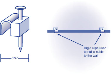
When
you’re installing cables, be gentle. Don’t pull, kink, or stretch them.
Don’t bend them sharply around corners; you should allow at least a
1-inch radius for bends. Don’t staple or crimp them. To attach cables to
a wall or baseboard, use rigid cable clips that don’t squeeze the
cable, as shown in Figure 1. Your local electronics store or hardware store can sell you the right kind of clips.
Keep network cables
away from AC power wiring and away from electrically noisy devices such
as arc welders, diathermy machines, and the like. (I’ve never actually
seen a diathermy machine, but I hear they’re trouble.)
Wiring with Patch Cables
If your computers are close together and you can
simply run prefabricated cables between your computers and switch,
you’ve got it made. Buy CAT-5 (or better) cables of the appropriate
length online or at your local computer store. Just plug (click) them
in, and you’re finished.
If you have the desire and patience, you can
build custom-length cables from crimp-on connectors and bulk cable
stock. Making your own cables requires about $75 worth of tools, though,
and more detailed instructions than I can give here. Making just a few
cables probably doesn’t make buying the tools worthwhile.
Factory-assembled cables are also more reliable than homemade ones
because the connectors are attached by machine. They’re worth the extra
few dollars.
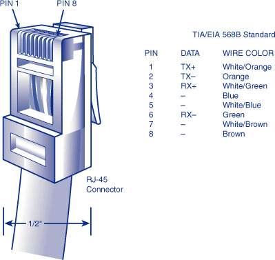
For the ambitious or parsimonious reader, Figure 2 shows the correct way to order the wires in the connector.
Installing In-Wall Wiring
In-wall
wiring is the most professional and permanent way to go. However, this
often involves climbing around in the attic or under a building,
drilling through walls, or working in an office telephone closet.
Personally, I find it a frustrating task and one I would rather watch
someone else do. Hiring someone to get the job done might cost $30–$75
per computer, but you’ll get a professional job, and if you consider
that the price of network cards has gone down at least this much in the
last 10 years, you can pretend that you’re getting the wiring thrown in
for free.
Tip
Look in the Yellow Pages
under “Telephone Wiring,” and ask the contractors you call whether they
have experience with network wiring. |
Note
To pick a technical nit
here, the modular connector used in networking is really called an 8P8C
connector. The “true telephone RJ45” connector is slightly different,
and not compatible. If you’re buying RJ45 connectors, just make sure
that the package says that the connectors are for networking use. |
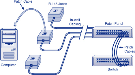
In-wall wiring is brought out to network-style
modular jacks mounted to the baseboard of your wall. These RJ-45 jacks
look similar to telephone modular jacks but are wider. You need patch
cables to connect the jacks to your computers and switch, as shown in Figure 3.
Connecting Just Two Computers
If
you’re making a network of just two computers, you might be able to
take a shortcut and eliminate the need for a network switch or
additional special hardware. If you want to add on to your network
later, you can always add the extra gear then.
Note
Microsoft is encouraging
the use of a special USB Cable for use by the Windows Easy Transfer
program, for people who don’t have a network. But, you can just as
easily (and much less expensively) use an Ethernet crossover cable. |
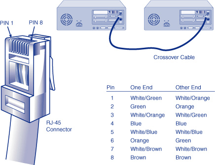
If you are connecting two computers, simply run a special cable called an Ethernet crossover cable
from one computer’s network adapter to the other, and you’re finished.
This special type of cable reverses the send and receive signals between
the two ends and eliminates the need for a switch. You can purchase an
Ethernet crossover cable from a computer store or network supply shop,
or you can make one, as shown in Figure 4.
Tip
Be sure that your
crossover cable is labeled as such. It won’t work to connect a computer
to a switch, and you’ll go nuts wondering what’s wrong if you try.
Factory-made models usually have yellow ends. When I make them myself, I
draw three rings around each end of the cable with a permanent-ink
marker. If you have a cable that you’re not sure
about, you can tell what kind of a cable it is by looking at the colors
on the little wires inside the clear plastic connectors at the two ends.
Considering just the colors on the wires, without regard to whether the
colors are solid or striped: If you can
see that each color is in the exact same position at both ends of the
cable, in the arrangement “AABCCBDD,” you have a standard Ethernet patch
cable. If a pair of wires that is
together at one end of the cable is split apart at the other end (that
is, if one end has the pattern AABCCBDD and the other has BBACCADD) you
have an Ethernet crossover cable. If the
pairs of wire are all split symmetrically around the center of the
connector (that is, if the pattern is ABCDDCBA), the cable is a
telephone cable and not an Ethernet cable. You can’t use this type of cable for networking.
|
Connecting Multiple Switches
You
might want to use more than one switch to reduce the number of long
network cables you need if you have groups of computers in two or more
locations. For example, you can connect the computers on each “end” of
the network to the nearest switch, and then connect the switch to a main
switch. Figure 5 shows a typical arrangement using this technique.
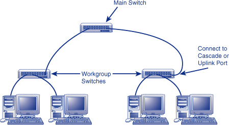
Note
A switch’s uplink or cascade
port is a connector designed to be connected to another switch or hub.
Some switches have a separate connector for this purpose, whereas others
make one of the switch’s regular ports do double-duty by providing a
switch that turns the last switch port into a cascade port. Refer to
your switch’s manual to see what to do with your particular hardware. |
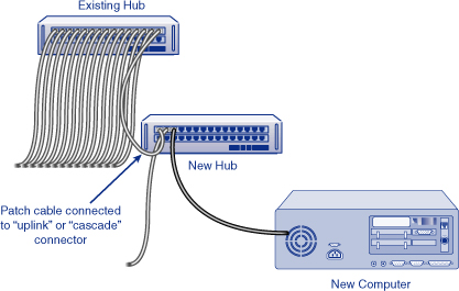
If you need to add a computer to your LAN and
your switch has no unused connectors, you don’t need to replace the
switch. You can just add a switch. To add a computer to a fully loaded
switch, unplug one cable from the original switch to free up a port.
Connect this cable and your new computer to the new switch. Finally,
connect the new switch’s cascade port to the now free port on the
original switch, as shown in Figure 6.